Repairing corrosion on a modern-era Lionel locomotive tender
On our previous page, we discussed the discovery of corrosion on the bottom of a modern era Lionel Hudson locomotive tender (figure 4). Next, we have to disassemble and remove all the parts from the tender floor so we can repair the damage.

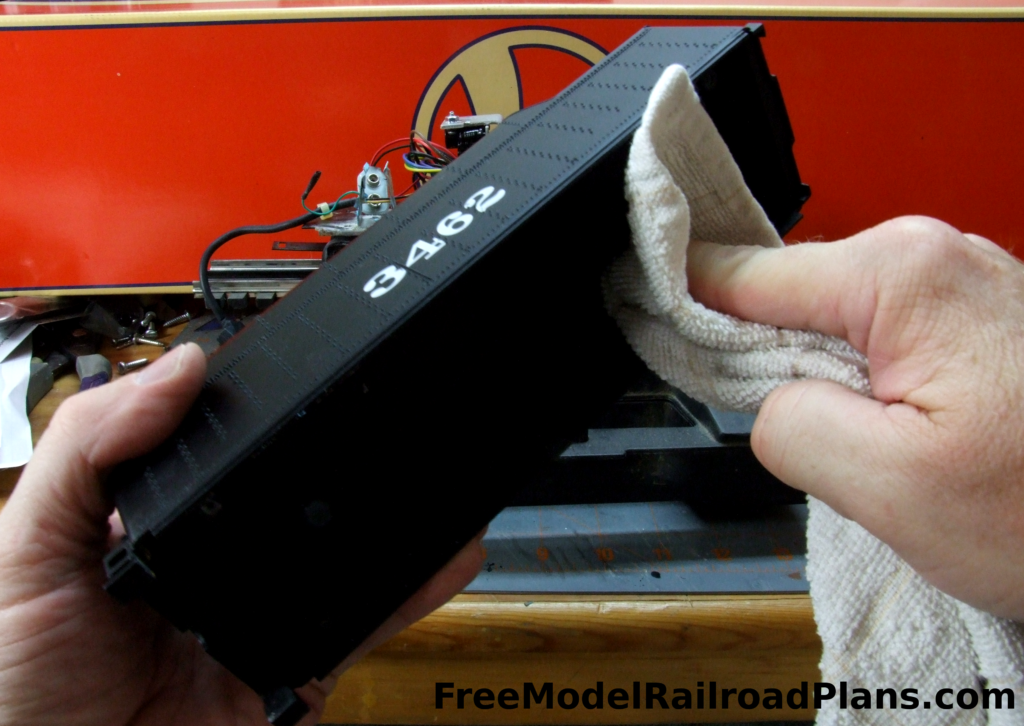
Before continuing with the disassembly, we wiped out the interior of the tender shell first with a rag wetted with 91% isopropyl alcohol (figure 5) to see if there was any damage beyond to the tender floor.

We continued cleaning the tender shell, using a cotton swab wetted with 91% isopropyl alcohol to get into tight corners the rag could not reach. Luckily there was no damage to the tender shell (figure 6).

All the items attached to the tender floor need to be removed, and some items must be removed first to access other items. We simply started with the screws we could easily reach, so we began with the screws mounting the volume control (figure 7).
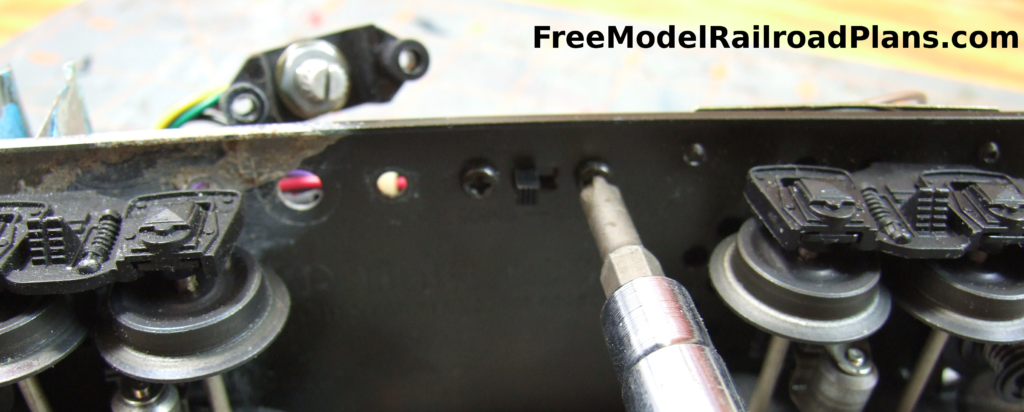
Next in line, we removed the on/off switch for the sound system (figure 8).

Removing the speaker must be done from the top of the tender floor. Note: the speaker blocks access to the screw securing the rear truck (figure 9).

Even after the speaker is removed, there is still a power wire going through the tender floor that will have to be removed (figure 10).

The screw fastening the forward truck is removed. Note there is also a power wire here that goes through the tender floor.
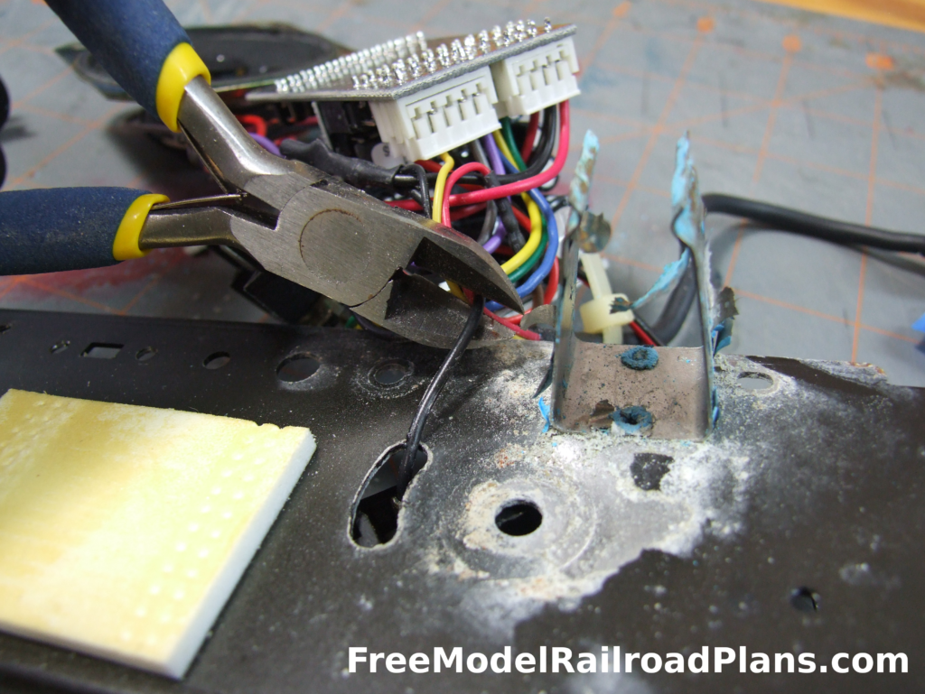
We decided that the easiest way to deal with the power wires was to cut them leaving enough length above the tender floor that we can later reconnect them with wire nuts.
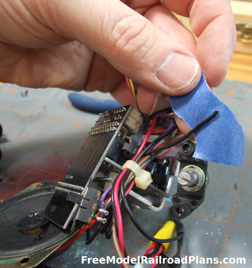
After cutting the power wires, we marked them with blue tape, writing the name on it.
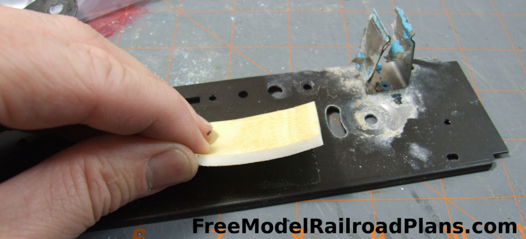
The circuit board for the sound system is mounted to the tender floor with a piece of two-sided sticky foam tape.

We wrapped the sticky foam tape in a piece of release paper from the back of a sticker we had laying about. We always try to reuse as many of the original items when we do repairs, even if it’s just a piece of foam tape. We want to return the item to as close to original condition as is possible.
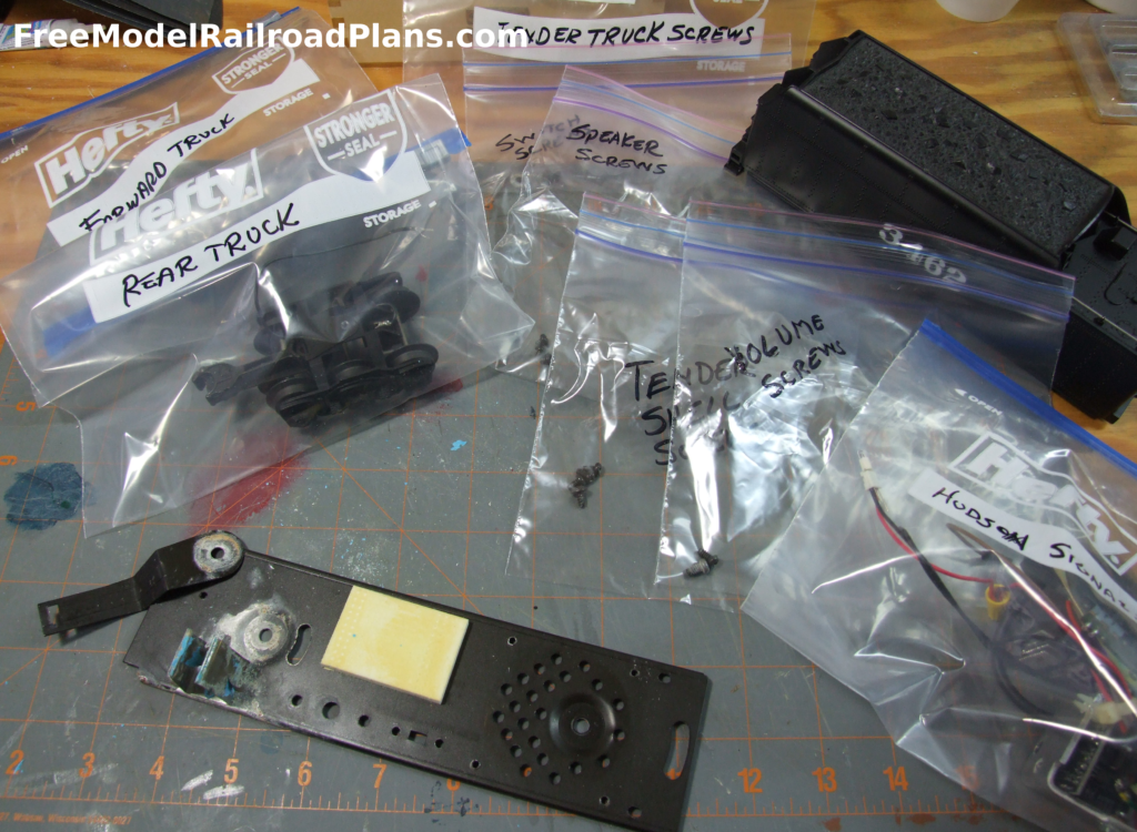
I should have pointed this out earlier, but, since we plan to reuse as many parts as possible, it’s a good idea to store each of them in a separate labelled bag so as to not mix them up during reassembly.