Invisible Track Power Connections
For Lionel Tubular O Gauge Model Railroad Track
Hide Power Lockons for a More Realistic Look
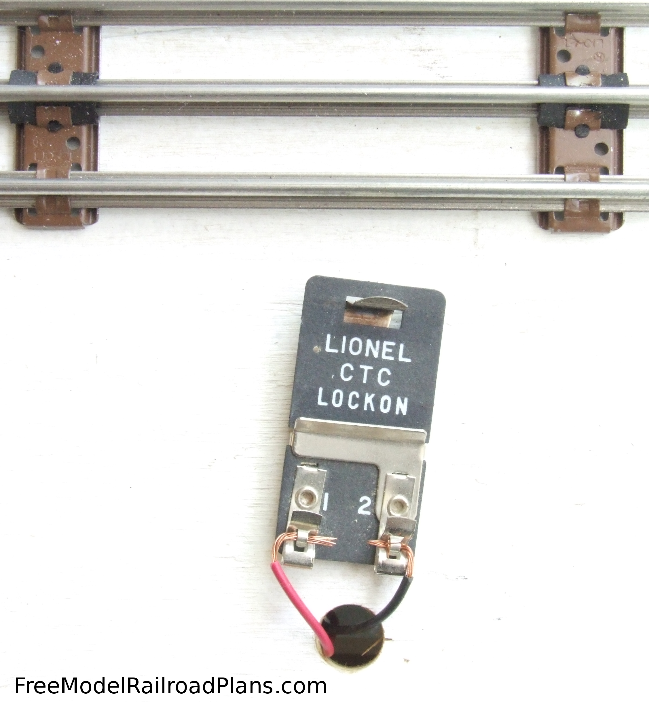
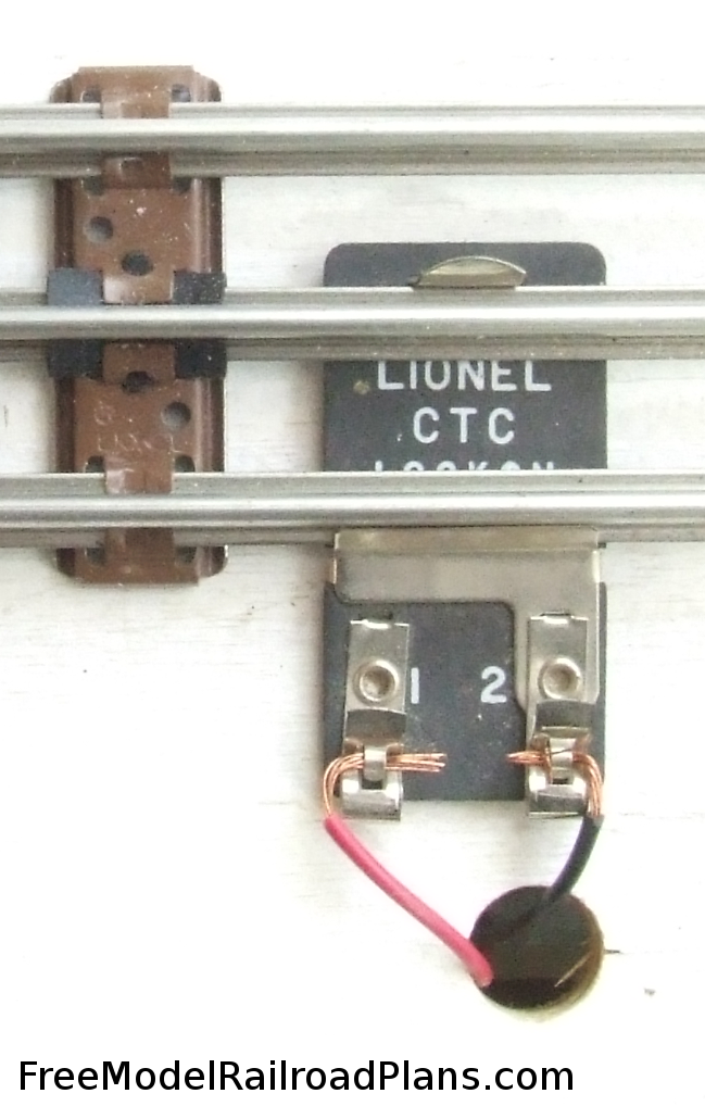
If you’ve ever built a model railroad with O Gauge tubular track, you’ve no doubt seen the Lionel CTC Lockon (Figure 1). These handy devices clip onto O Gauge tubular model railroad track (Figure 2) to bring the power from your transformer to your trains. They provide a sturdy connection with good electrical contact, but they stick out like a sore thumb, especially if you plan on ballasting the track with gravel. They also can come loose if something hits them, or if, over time, they just lose their springiness they can slip off the track, or the wires slip loose from the terminals.
For our O Gauge Model Railroad Layout Project for a Spare Bedroom, we used a way to connect power to the track that is totally invisible from above – we soldered the power wires onto the bottom of the rail. Even if you’ve never soldered before, this technique is easy, eliminates the need for Lionel CTC Lockons, and reduces the chances a wire will come loose from the rail and break electrical contact.
We start out with two lead wires about 18 inches each: red for the center “hot” rail, and black for the outside “ground” rails. You can use any color you like, just be consistent so you don’t have to remember later which wire is soldered to which rail, as you would have to remove the track from the roadbed to find out. A simple matter of loosening a couple screws, unless you have already ballasted the track, in which case, much prying and cursing will be involved. We are using heavier wire for our leads than that supplied with the lockon, which looks to be about 22 gauge. Our heavy 14 gauge stranded wire can handle more current with less resistance, which will come in handy when our bigger locomotives, which can draw a lot of current, are climbing the grade of our over/under figure 8.
Just as you must strip the insulation from the wires before inserting them into the Lionel CTC Lockon, you must strip them before soldering (Figure 3).
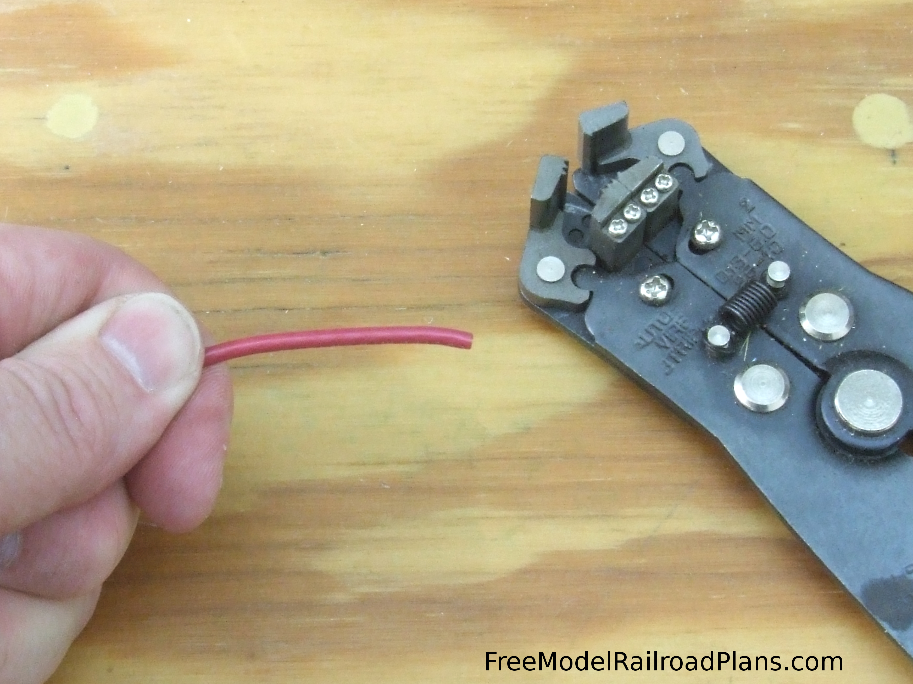
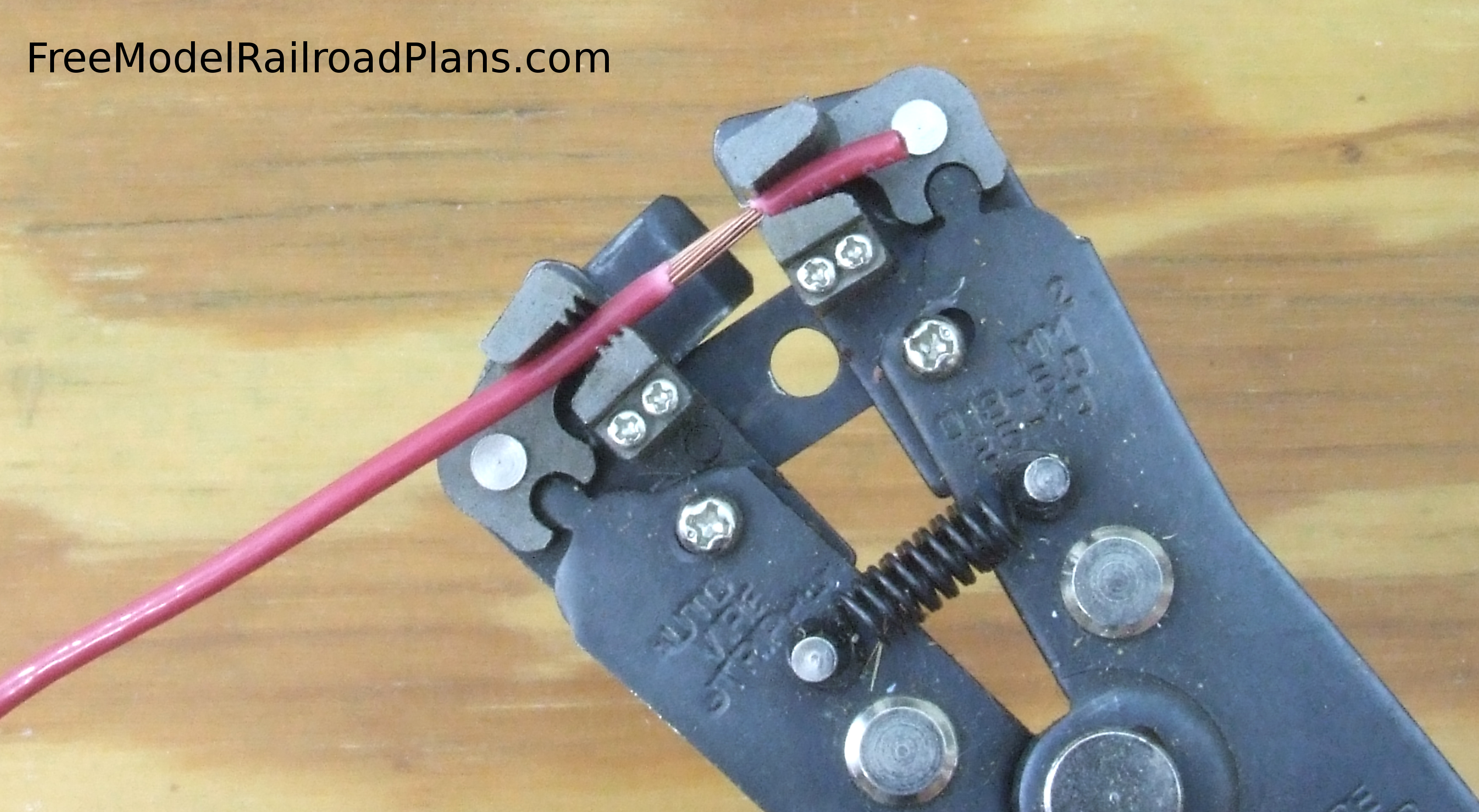
While you can strip wire with an Xacto knife by lightly rolling it back and forth until it cuts through the plastic insulation, and then removing the piece of insulation by sticking your fingernail into the cut and pulling with your finger and thumb, I use a handy automatic wire stripper (Figure 4) that grabs the insulation, cuts it, and then pulls it off. This tool makes short work of the many connections we will need to make in wiring our O Gauge Model Railroad Layout Project for a Spare Bedroom.
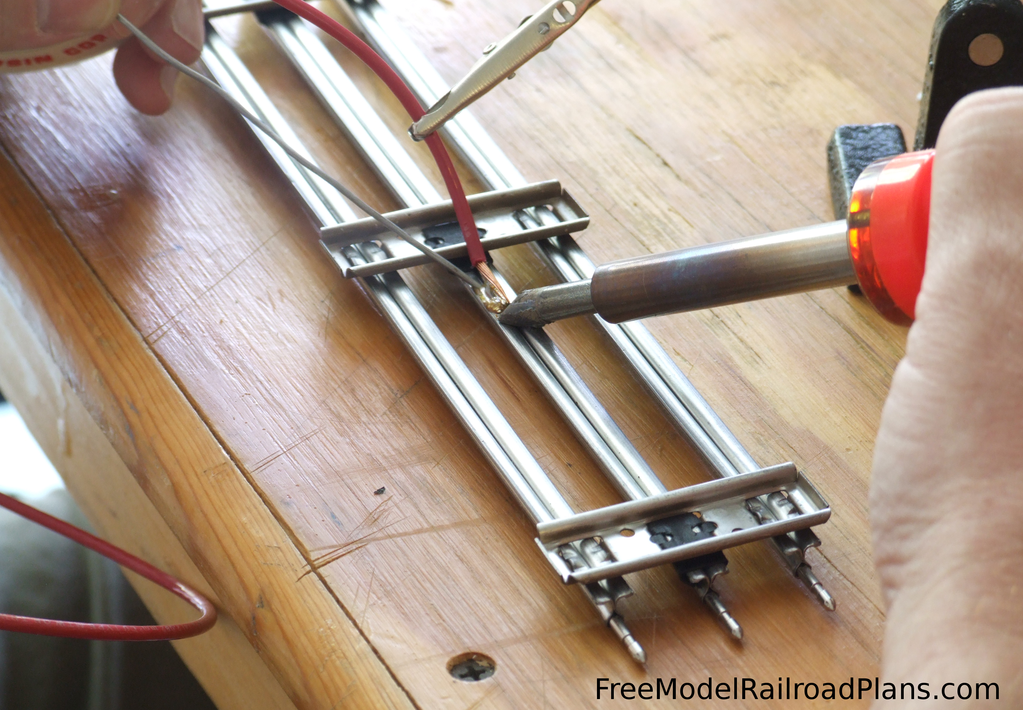
As shown in Figure 5, we used a “third hand” with an alligator clip at the end of it to hold the red “hot” wire in contact with the center rail while we heated the rail at the tip of the wire with a small soldering iron. A soldering iron is another inexpensive tool that will come in very handy not only on this project, but many others around the house. Once the rail and wire get hot, touch a thin rosin-core solder wire to the rail and the end of the bared wire away from the soldering iron. This makes sure the heat of the wire and rail, not the soldering iron, is what causes the solder to melt, ensuring a good solder joint. If the solder is melted by the soldering iron before the rail and wire are hot enough, you may get a “cold” solder joint that doesn’t conduct electricity well, and is subject to breaking loose. When the solder begins to melt, the rosin-core flux will cause the melted solder to be drawn into the joint. Once the joint is filled with solder, remove the solder wire and soldering iron and let it cool.
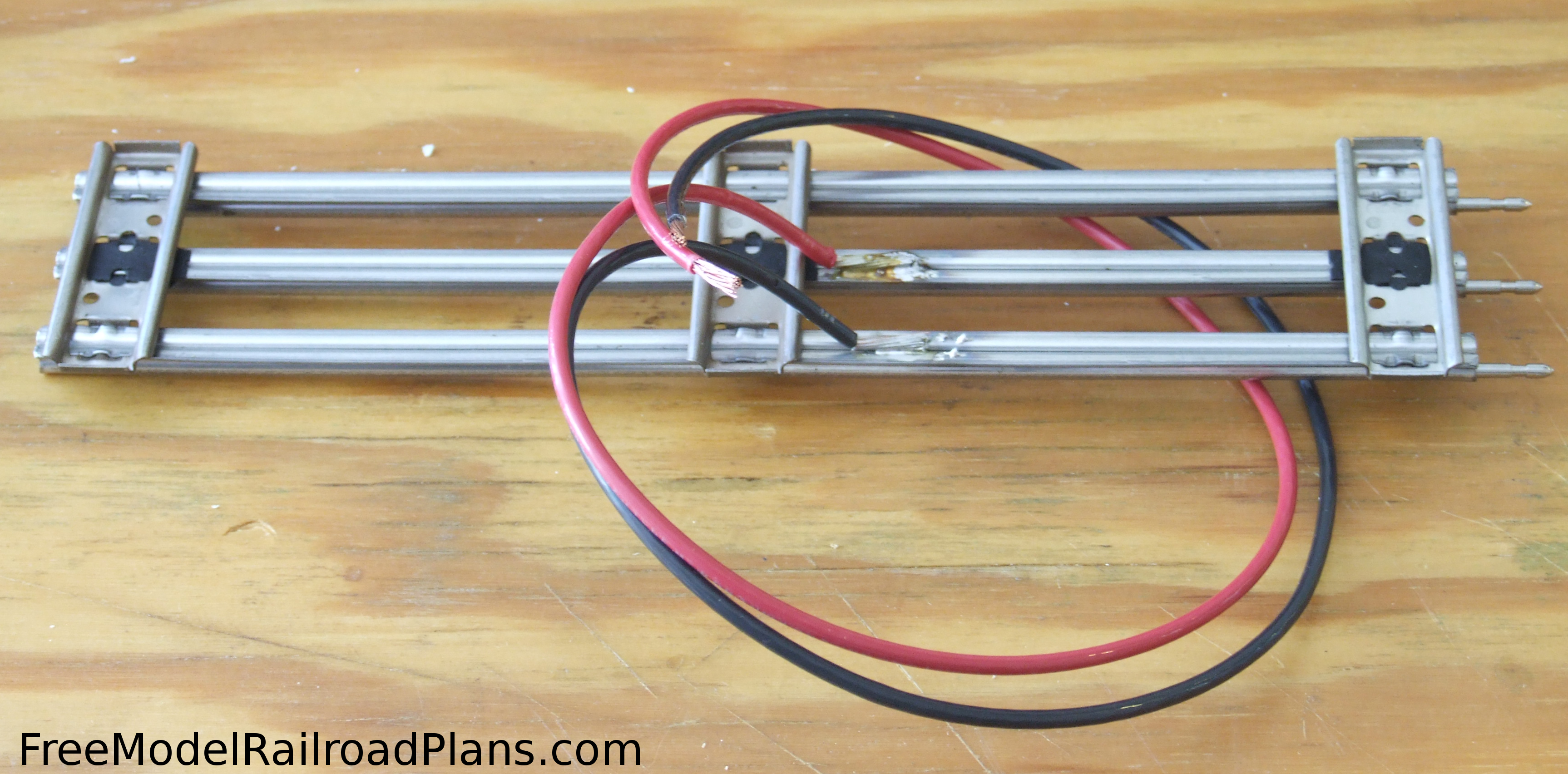
Repeat the process with the black “ground” wire, attaching it with the bare wire running the same direction as the other lead, and close to the part of the track section where the other lead is attached, as shown in Figure 6. This way you can drill just one hole for both wires to go beneath the roadbed. Only one black “ground” wire needs to be attached, as the metal ties of the track create an electrical connection between the two outer rails. Small fiber or plastic shims between the metal tie and the center rail keep it electrically isolated from the outer rails.
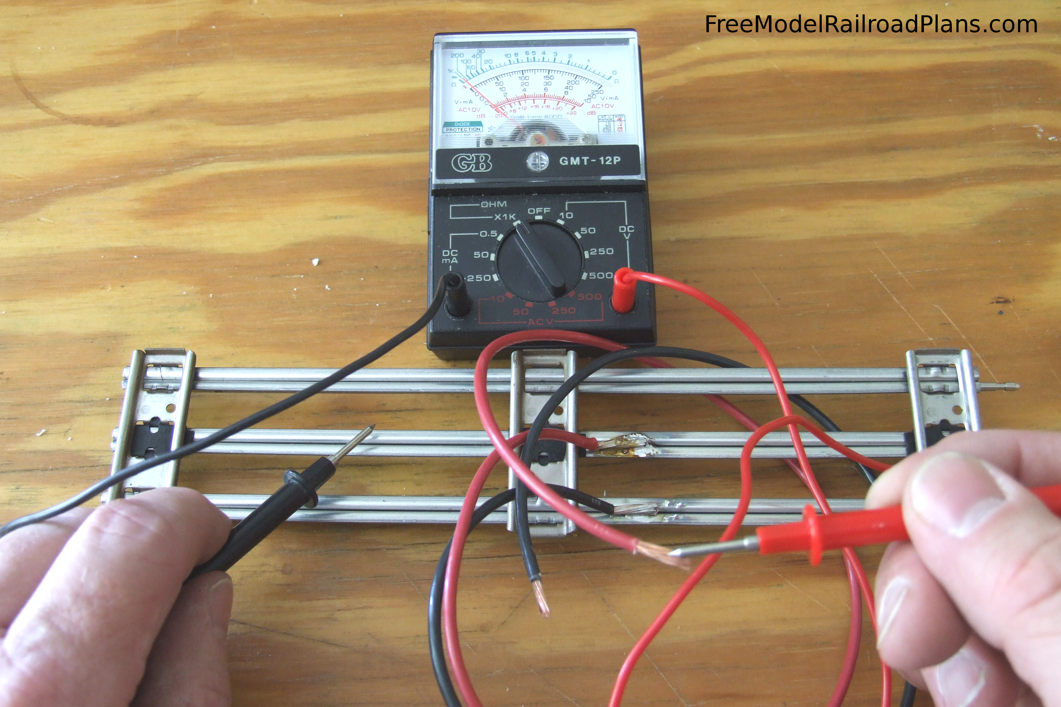
After the solder joints have cooled, it’s a good idea to check their electrical conductivity with a multi-meter. Better to find a bad solder joint now than after the track has been screwed down to the roadbed! Set the meter to read electrical resistance (measured in Ohms), touch one meter lead to the far end of the wire you just soldered on, and the other down the track section a bit on the rail to which that wire is soldered, as shown in Figure 7. The needle should read 0 (zero) Ohms of resistance if your solder joint is good. In the photo, the black meter lead had not quite touched the center rail when the camera shutter fired, but when it did, the needle shot to the right side of the meter, indicating there was no impedance in the connection.
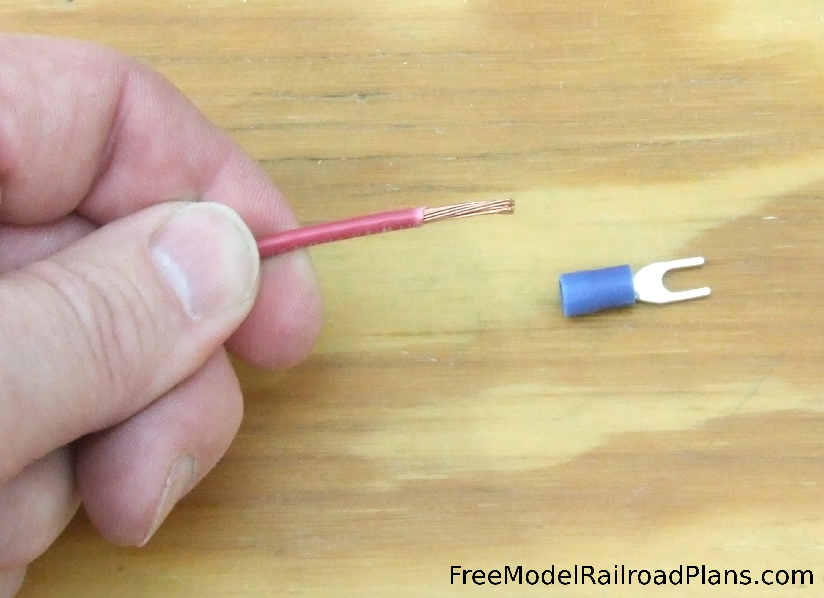
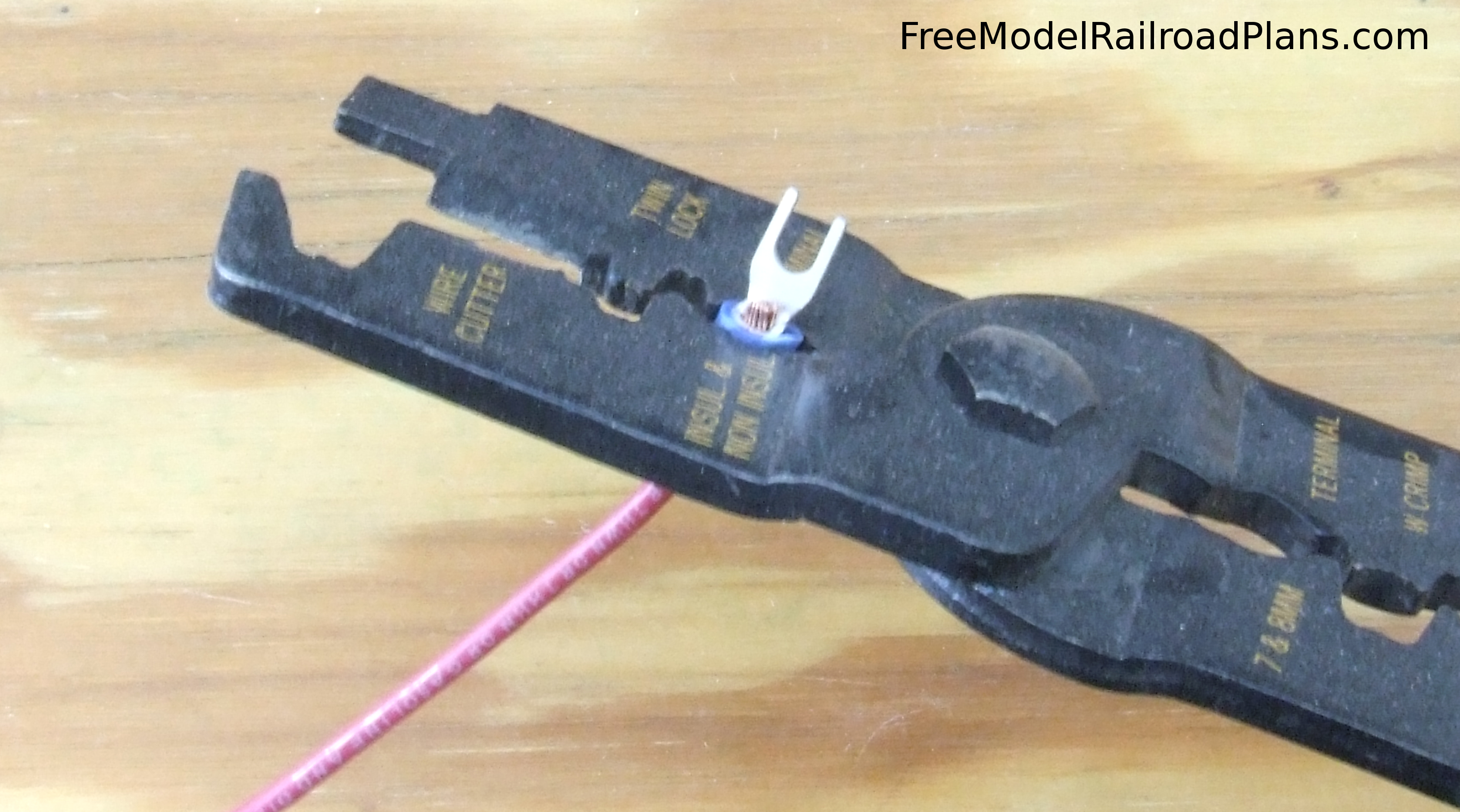
On the other end of the soldered leads, we will install spade connectors, as shown in Figure 8. While soldering gives you the sturdiest joint, we will be making our next connections under the benchwork, working over our heads, a situation in which using a soldering iron is just asking for a hot drop of liquid solder to drop on you. Also, a soldered joint is a permanent joint, so any changes to the wiring later would require wire cutters. In keeping with our modular benchwork design, the spade connectors will allow us to disassemble or change wiring later without difficulty of cutting and resoldering. To attach the spade connectors to the ends of our leads, we use a crimping tool as shown in figure 9. This tool works much better than pliers, as it has teeth than pinch into the metal of the spade connector rather than just crushing it, making for a very secure joint.
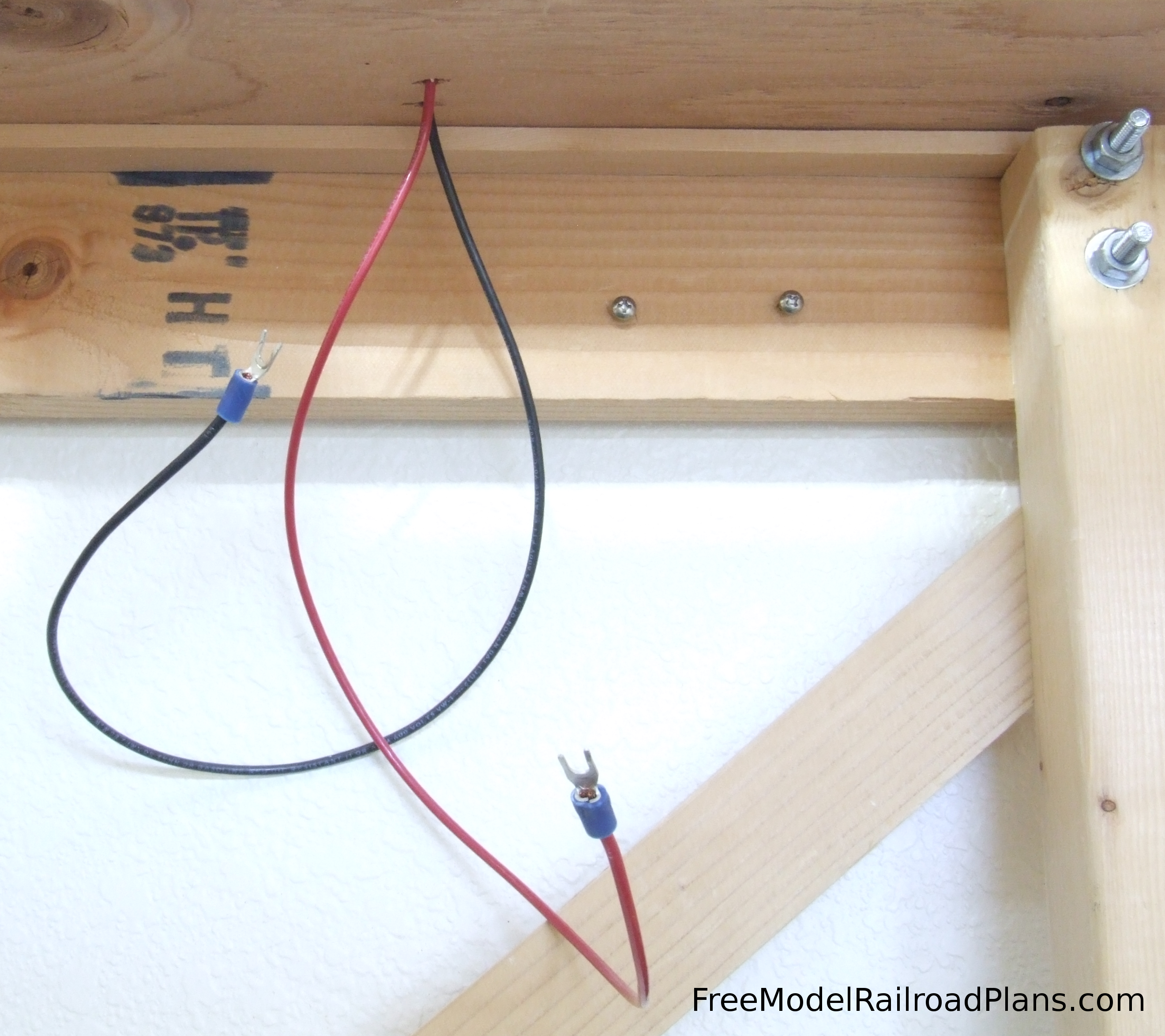
Next we drilled a hole through the roadbed and subroadbed where the wires will be when the track is attached to it. Make sure the hole is big enough for the spade connectors to fit through. If you feed them through the hole one at a time you can get away with using a slightly smaller hole than you would need to cram them both through at one time. What you end up with after the track is attached to the roadbed is dangling power leads under the benchwork as shown in Figure 10.
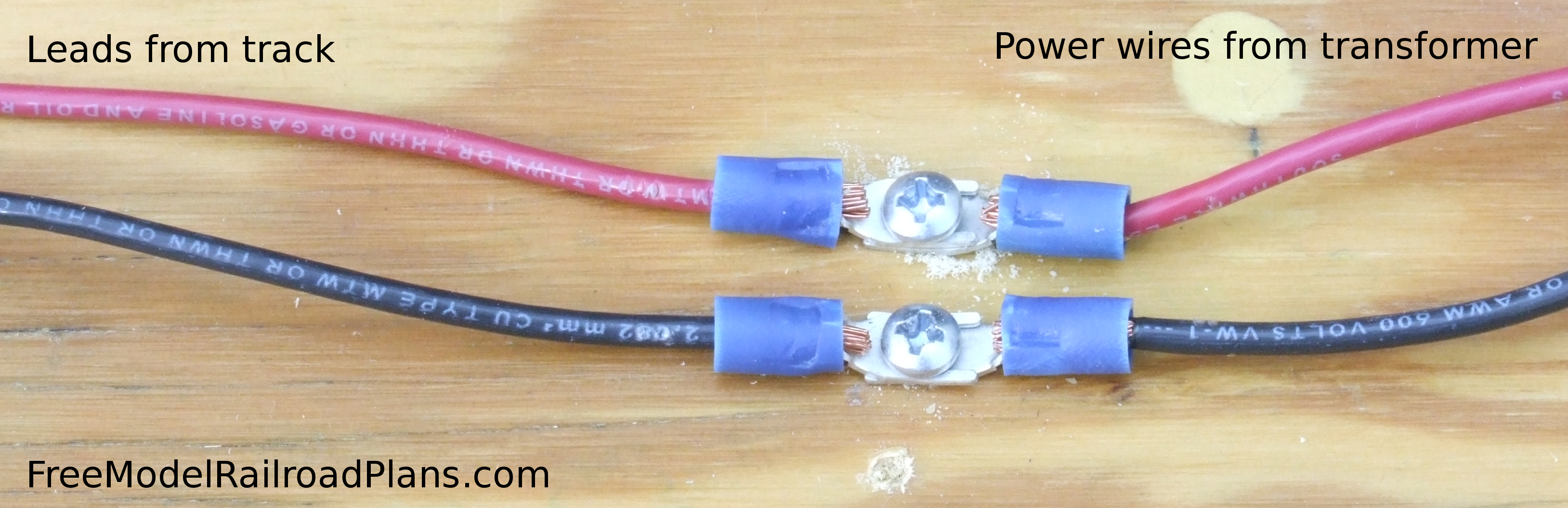
The easiest way to connect these to the power wires coming from the transformer is to just drive two screws part of the way into the benchwork, place the spade connectors from the track leads and the transformer leads under the head of the screw, and lock them together by tightening the screws down on the spade connectors, as shown in Figure 11. Because we are working with low voltage, you can get away with this type of connection, however, we DO NOT recommend this method, as it would be easy for a stray wire to short circuit this setup.
We will, instead, be using barrier block terminal strip connectors where we need to make connections throughout the O Gauge Model Railroad Layout Project for a Spare Bedroom. As shown in Figure 12, these handy little devices have a plastic base with plastic walls between the connections to keep them from short circuiting.
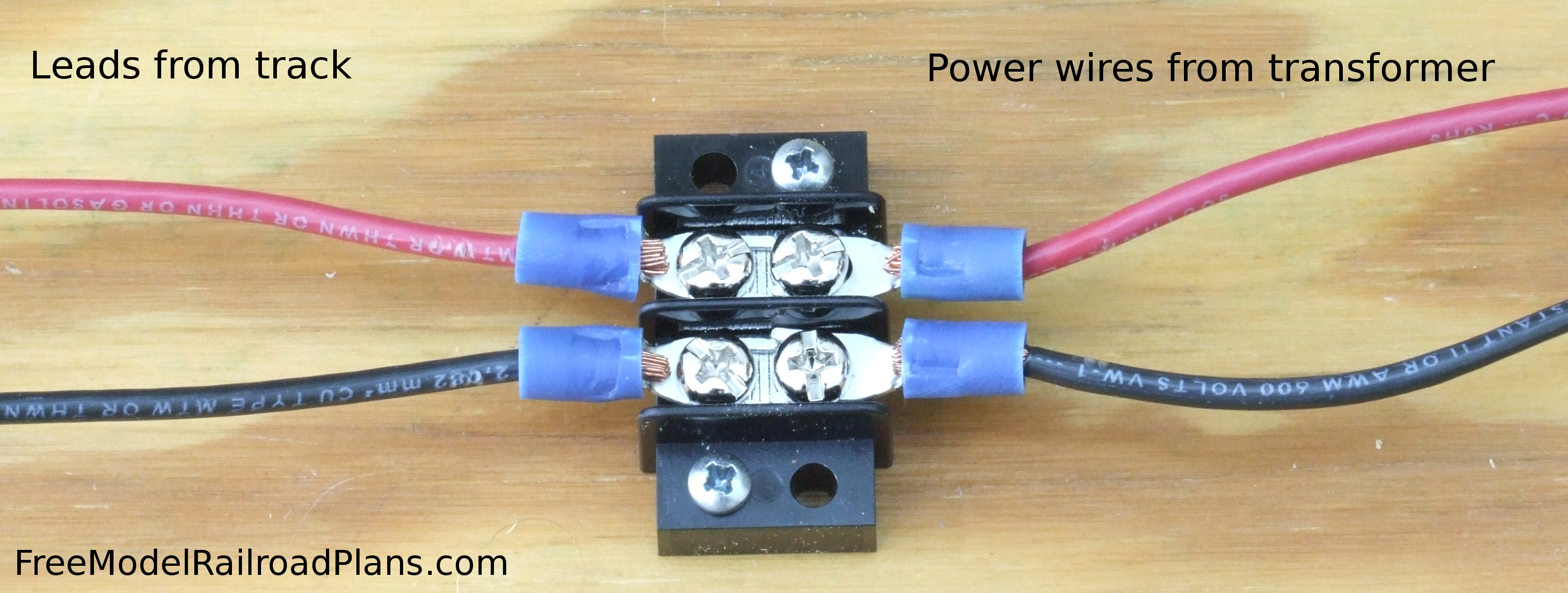
The track power leads connect to one side of the terminal strip, and the transformer power leads (note we used the same color wire to visually confirm which wire needs to connect to which) to the other side of the terminal strip. A metal bus connects the left and right connector screws so you get good current through your connections. We will be using a lot of these devices for connections around the benchwork of our O Gauge Model Railroad Layout Project for a Spare Bedroom. They are available with many different configurations of terminals – in the control panel we will be using some that have eight terminals on each side, which – along with toggle switches – will allow two different transformers to be used to operate two different trains on the layout at once.
Please Support FreeModelRailroadPlans.com
FreeModelRailroadPlans.com is entirely user supported. If you find something of value here, please “pay it forward” and help us keep the site operating by a secure donation through PayPal (PayPal account is not required), or by shopping with our advertisers.
Thank you for your support!
Where do I get the crimping tool and spade connectors? Willing to donate at least $ 5.00
Thanks for visiting the website! I found the crimping tool, spade connectors, wire, and even the soldering iron at a regular hardware store – I think it was Lowe’s. Look for a “low voltage” section in the electric supplies section. It will usually be separated a bit from the typical high voltage electrical supplies designed to wire a house.
Can one use narrow butt connectors to attach to runs of wires.
If narrow butt connectors are the connectors we euphemistically refer to as “suitcase connectors” due to their resemblance, yes you can use them. I often did in the past, but found myself cutting them out when I needed to change wiring (sometimes for expansions, sometimes to correct mistakes). I’ve also seen that suitcase connectors also seem prone to connection failure over time, perhaps due to expansion and contraction throughout seasonal changes, or maybe just vibration. I use the barrier strips as an “open suitcase,” where I run my bus wires from one barrier strip to the next, and then tap into the barrier strip with lead wires on top of the bus wires. This has worked well even on mobile modules that get an unreasonable amount of jostling during movement and installation, and which I formerly soldered all connections.
How many connections can one do before you need Togo back and reattached to the tranformer. Can one Circle the layout and connect at junctions to advance the power from the transformer to sections of the tract run.